Jewel Nath
← Home

OrbiBot

At Orbitax, I build OrbiBot in my free time, on the way to a telepresence robot for the office. V1 is the one I built: I welded its frame, wired it, wrote its firmware and its ROS 2 software, and gave it an AI agent. V2 was designed in CAD and then parked. V3, Orbitax's office telepresence robot, is designed and simulated.

2025 to nowMy part: everything, from the welding and wiring to the firmware, ROS 2, the dashboard and the agent

What it shows

Robotics software
ROS 2 Jazzy, LiDAR mapping with slam_toolbox, an EKF, and Nav2 navigation with MPPI for mecanum wheels
Embedded
My own STM32 motor firmware: PID at 100 Hz per wheel, with a 2-second safety stop
AI agent
58 robot tools for Gemini, Claude, Kimi or a local model, and for any client through an MCP server
Hardware design
A frame welded by hand; V2's platform drawn in FreeCAD and its controller board in KiCad

V1 · Built and driven

The robot I built

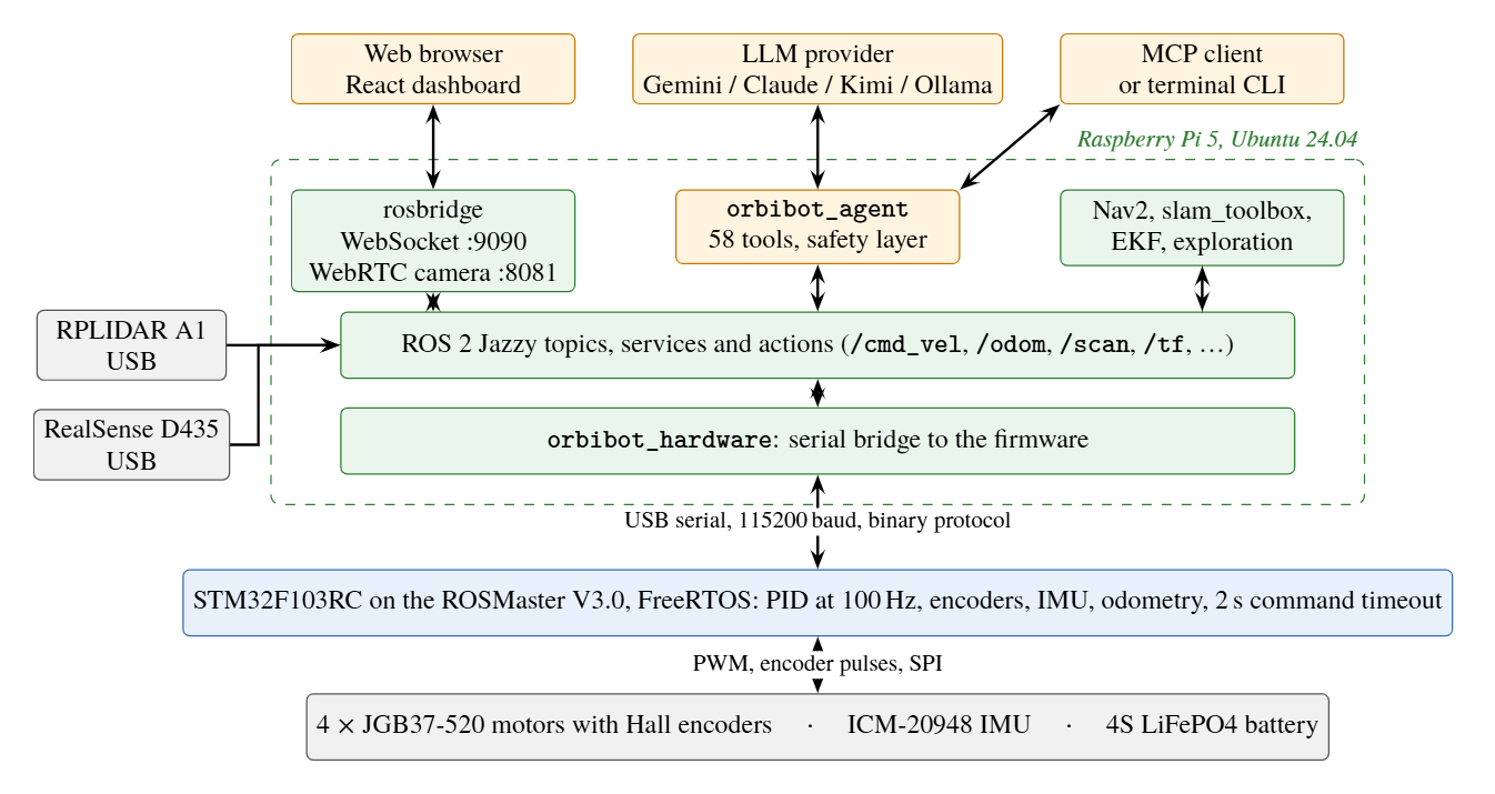
A welded stainless-steel frame on four mecanum wheels, so it drives in any direction and turns on the spot. Two computers share the work: an STM32 motor board runs everything with a deadline, and a Raspberry Pi 5 runs everything that needs a map, a model or a network.

Pi 5, gamepad and a SLAM map · Jul 2025

Datasheet

Frame
Stainless steel, welded by hand
Wheels
Four 100 mm steel mecanum wheels
Motors
Four JGB37-520 geared DC motors, 1:30, with Hall-effect encoders
Motor board
STM32F103 (Yahboom ROSMaster V3.0), running my own firmware
Computer
Raspberry Pi 5, 8 GB, Ubuntu 24.04
Sensors
RPLIDAR A1; later a RealSense D435 at the front; ICM-20948 IMU
Power
4S LiFePO4 pack of 32140 cells, 12.8 V
Software
ROS 2 Jazzy, in 12 packages I wrote

How it works

rosbridge · tool calls
binary serial protocol
PWM · encoder counts

Two computers, one split

Everything with a deadline runs on the microcontroller; everything that needs a map, a model or a network runs on the Pi. Tap a part.

See the report's system diagram →

What I wrote

Firmware

My own firmware for the STM32 motor board, in place of the vendor's closed one: motor PID at 100 Hz, quadrature encoders, the IMU, wheel odometry, a binary serial protocol, settings kept in flash, and a 2-second timeout that stops the motors if the host goes quiet.

12 ROS 2 packages

An EKF that fuses wheel odometry with a Madgwick-filtered IMU, mapping with slam_toolbox and AMCL on saved maps, Nav2 with the MPPI controller in its omnidirectional mode, and a frontier explorer re-implemented in Python from m-explore-ros2.

The dashboard

React and TypeScript, reaching ROS 2 through rosbridge over a WebSocket, with the camera over WebRTC: battery, motors, odometry, the IMU, the live map, the camera, and driving. Every command goes through the same ROS 2 topics as everything else.

orbibot_agent

An AI layer with 58 robot tools that runs on Gemini, Claude, Kimi or a local model through Ollama, with three ways in: an HTTP API, a terminal client and an MCP server, and a safety layer on its direct motion tools.

In video

Short silent clips from the build log. Tap one to play it.

Building it

  • Jun 2025

    Welding the stainless-steel frame, with the mecanum wheels fitted

  • Jun 2025

    The first electronics on the frame: the LiDAR, the motor board and a blue underglow

  • Jun 2025

    The first build on a desk

  • Jun 2025

    A motor test, with the wheels lifted off the desk

Mapping and driving

  • Jul 2025

    On its Raspberry Pi 5, with its gamepad and a SLAM map in RViz

  • Jan 2026

    A map of my home in RViz, then the robot driving on the floor

  • Jan 2026

    A second run at home

Checking each sensor

  • Jan 2026

    Tilted by hand: the model in RViz tilts with the IMU

  • Jan 2026

    A wheel turned by hand, read by its encoder

  • Jan 2026

    Wheels turned by hand: the wheel frames turn in RViz

  • Jan 2026

    A card moved in front of the LiDAR: the scan changes in RViz

The dashboard

  • Feb 2026

    Driving from the browser, with the live camera and the map

  • Feb 2026

    Mapping my home from the browser

On the bench

Measured on the bench, with the wheels off the ground, as the report describes.

how far chassis velocity was from the command
1.3–9.3 %
to stop after the last command, with a 2 s timeout
1.82–2.12 s
what the velocity clamp held a 3 m/s command to
1.02 m/s
between the four motors at the speed limit
0.1 %

The build, in photos

  1. Jun 2025

    Welding the frame.

  2. Jun 2025

    The frame from above, with the LiDAR.

  3. Jun 2025

    The first electronics, with a blue underglow.

  4. Sep 2025

    The Raspberry Pi 5 build.

  5. Nov 2025

    Rebuilt, with a RealSense D435 at the front.

  6. Jan 2026

    Navigating on a map of my home, watched in RViz.

What I learned

Put the deadlines on the microcontroller

PID, encoders and the stop timeout run on the STM32. By design, a busy Pi or dashboard shouldn't make the wheels stutter (not yet tested under load), and the next robot's computer can change without touching the firmware.

A 2D LiDAR sees one flat slice

A table top above it or a low box below it does not exist to the LiDAR. That is why V1 got a depth camera.

Maps in a browser are a bandwidth problem

The dashboard was designed around what the robot has to serialise and send, not around how the page looks.
The report

Technical report · v1.1 · Zenodo · Oct 2026

OrbiBot V1: A Mecanum Mobile Robot with Microcontroller-Level Real-Time Control, a ROS 2 Navigation Stack, and a Tool-Using LLM Agent — Design and Bench Evaluation

J. Nath

DOI 10.5281/zenodo.23752389

V2 · Designed, then parked

A lighter platform, on paper

V1's hand-welded steel frame had alignment problems: the wheels never sat quite straight, and the frame was heavy. V2 replaced it with a body of light 4 mm acrylic plates, designed in CAD to be laser cut, and its own controller board.

The CAD layout turning once. The colours are for display only.

Datasheet, as designed

Size
280 × 260 mm
Mass
About 5.6 kg, on paper
Wheels
V1's four 100 mm mecanum wheels
Computer
A Beelink SER5 Pro mini PC on a rear plate, through a 19 V boost
Sensors
RPLIDAR A1 on top, RealSense D435 low at the front, ToF sensors front and rear
Power
4S LiFePO4 pack with its BMS, on the bottom deck
Controller
My own board: an STM32F446RET6 with four DRV8874 motor drivers

Where the board stopped

  • Schematic5 of 5 sheets

    ERC with no errors

  • Parts placed176 of 176 parts

    Ground planes poured, DRC with no errors

  • Connections routed0 of 304 connections

    Routing had not started

On 10 September 2026 the goal changed to a different robot. I archived V2 with every decision and its reasoning: parked, not cancelled, instead of left half finished.

The CAD, four ways

Its own controller board

Next: Robot Niko

A life-size humanoid assistant I built with my team in 2022, with its own report.